
In his book UML Distilled – A Brief Guide to the Standard Object Modeling Language Martin Fowler describes three ways he sees UML being used:
- UML as sketch: Developers use UML to communicate some aspect of a system. These sketches can be used in both forward (i.e. devising new systems) as well as reverse (i.e. understanding existing systems) engineering. Sketches are used to selectively talk about those parts of the system of interest. Not all of the system is sketched. Sketches are drawn using lightweight drawing tools (e.g. whiteboards and marker pens) in sessions lasting anything from a few minutes to a few hours. The notation and adherence to standards is non-strict. Sketching works best in a collaborative environment. Sketches are explorative.
- UML as a blueprint: In forward engineering the idea is that developers create a blueprint that can be taken and built from (possibly with some more detailed design first). Blueprints are about completeness. The design/architecture should be sufficiently complete that all of the key design decisions have been made leaving as little to chance as possible, In reverse engineering blueprints aim to convey detailed information about the system, sometimes graphically. Blue prints require more sophisticated modelling tools rather than drawing tools. Blueprints are definitive.
- UML as a programming language: Here developers draw UML diagrams that are compiled down to executable code. This mode requires the most sophisticated tooling of all. The idea of forward and reverse engineering does not exist because the model is the code. Model Driven Architecture (MDA) fits this space.
In practice there is a spectrum of uses of UML which I’ve shown below in Figure 1. In my experience very few organisations are up at level 10 and I would say most are in the range 3 – 5. I would classify these as being those folk who use UML tools to capture key parts of the system (either in a forward or reverse engineering way) and export these pictures into documents which are then reviewed and signed-off.
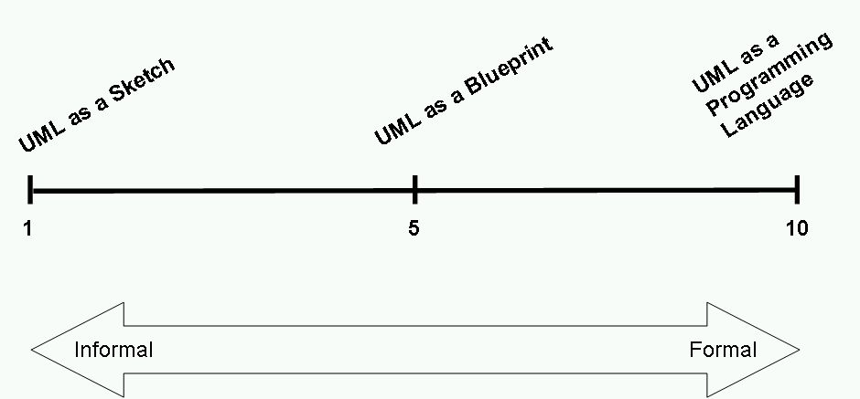 |
| Figure 1 |
An interesting addition to the ‘UML as sketch’ concept is that at least two vendors that I know of (IBM and Sparx) are offering ‘sketching’ capabilities within their modeling tools. In Rational Software Architect the elements in a sketch include shapes such as rectangles, circles, cylinders, stick figures that represent people, and text labels. Checkout this YouTube video for a demo. Unlike other types of models, sketches have only a few types of elements and only one type of relationship between elements. Also, sketches do not contain multiple diagrams; each sketch is an independent diagram. You can however move from a sketch to a more formal UML diagram or create a sketch out of an existing UML diagram so allowing you to work with a diagram in a more abstract way.
Below in Figure 2 is an example of a sketch for my example Hotel Management System, that I’ve used a few times now to illustrate some architectural concepts, drawn using the current version of Rational Software Architect. I guess you might call this an Architecture Overview used to show the main system actors and architectural elements.
 |
| Figure 2 |
I guess the ability to be able to sketch with modeling tools could be a bit of a double edged sword. On the one hand it means sketches are at least captured in a formal modeling environment which means they can be kept in one centrailsed repository and can be maintained more effectively. It also means they can potentially be turned into more formal diagrams thus providing a relatively automated way of moving along the scale shown in Figure 1. The downside might be that sketching is as far as people go and never bother to provide anything more formal. I guess only time will tell whether this kind of capability gains much traction amongst developers and architects alike. For my part I would like to see sketching in this way as a formal part of a process which encourages architects and developers to create models using this approach, get them roughly right and then turn them ino a more formal and detailed model.

Hi
Thanks for this all information about hotel management system i like it
Hotel Management System