You’re Building Me a What?

This week I’ve been attending a cloud architecture workshop. Not to architect a cloud for anyone in particular but to learn what the approach to architecting clouds should be. This being an IBM workshop there was, of course, lots of Tivoli this, WebSphere that and Power the other. Whilst the workshop was full of good advice I couldn’t help of thinking of this cartoon from 2008:

Courtesy geekandpoke.typepad.com

Just replace the word ‘SOA’ with ‘cloud’ (as ‘SOA’ could have been replaced by ‘client-server’ in the early nineties) and you get the idea. As software architects it is very easy to get seduced by technology, especially when it is new and your vendors, consultants and analysts are telling you this really is the future. However if you cannot explain to your client why you’re building him a cloud and what business benefit it will bring him then you are likely to fail just as much with this technology as people have with previous technology choices.

A Service Based Development Process – Part 4

The first three of these blog posts (here, here and here) have looked at the process behind developing business processes and services that could be deployed into an appropriate environment, including a cloud (private, public or hybrid). In this final post I’ll take a look at how to make this ‘real’ by describing an architecture that could be used for developing and deploying services, together with some software products for realising that architecture.The diagram below shows both the development time and also run-time logical level architecture of a system that could be used for both developing and deploying business processes and services. This has been created using the sketching capability of Rational Software Architect.

Here’s a brief summary of what each of the logical components in this architecture sketch do (i.e. their responsibilities):

  • SDLC Repository – The description of the SDLC goes here. That is the work breakdown structure, a description of all the phases, activities and tasks as well as the work products to be created by each task and also the roles used to create them. This would be created and modified by the actor Method Author using a SDLC Developer tool. The repository would typically include guidance (examples, templates, guidelines etc) that show how the SDLC is to be used and how to create work products.
  • SDLC Developer – The tool used by the Method Author to compose new or modify existing processes. This tool published the SDLC into the SDLC Repository.
  • Development Artefacts Repository – This is where the work products that are created on an actual project (i.e. ‘instances’ of the work products described in the SDLC) get placed.
  • Business Process Developer – The tool used to create and modify business processes.
  • IT Service Developer – The tool used to create and modify services.
  • Development Repository – This is where ‘code’ level artefacts get stored during development. This could be a subset of the Development Artefacts Repository.
  • Runtime Services Repository -Services get published hereonce they have been certified and can be released for general use.
  • Process Engine – Executes the business process.
  • Enterprise Service Bus – Runs the services and provides adapters to external or legacy systems.

Having described the logical components the next step is to show how these can be realised using one or more vendors products. No surprise that I am going to show how these map to products from IBM’s portfolio however clearly your own particular requirements (including whose on your preferred vendor list of course) may dictate that you choose other vendors products. Nearly all the IBM product links allow you to download trial versions that you can use to try out this approach.

  • Rational Method Composer – This enables you to manage, author, evolve, measure and deploy effective processes (SDLCs) tailored to your project needs. It is based on Eclipse. Rational Method Composer allows publishing to a web site so effectively covers the needs of both the SDLC Repository and SDLC Developer components.
  • IBM Business Process Manager – This is the latest name for IBM’s combined development and runtime business process server. As well as a business process runtime, ESB and BPM repository it also includes design tools for building processes and services.  The Process Designer allows business authors to build fully executable BPMN processes that include user interfaces for human interaction. The Integration Designer enables IT developers to develop services that easily plug into processes to provide integration and routing logic, data transformation and straight-through BPEL subprocesses. See this whitepaper for more information or click here for the IBM edition of the book BPM for Dummies. IBM Business Process Manager realises the components: Business Process Developer, IT Service Developer, Development Repository, Process Engine and Enterprise Service Bus.
  • WebSphere Service Registry and Repository – Catalogs, and organizes assets and services allowing customers to get a handle on what assets they have, making it easy to locate or distribute. Also enables policy management across the SOA lifecycle, spanning various domains of policies including runtime policies as well as service governance policies. Included in the Advanced Lifecycle Edition is
    Rational Asset Manager which provides life cycle management capabilities to manage asset workflow from concept, development, build, deployment, and retirement as well as Build Forge integration. WebSphere Service Registry and Repository realises the Development Artifacts Repository as well as the Runtime Services Repository.

So, there it is. An approach for developing services as well as an initial architecture allowing for the development and deployment of both business processes and services together with some actual products to get you started. Please feel free to comment here or in any of my links if you have anything you’d like to say.

A Service Based Development Process – Part 3

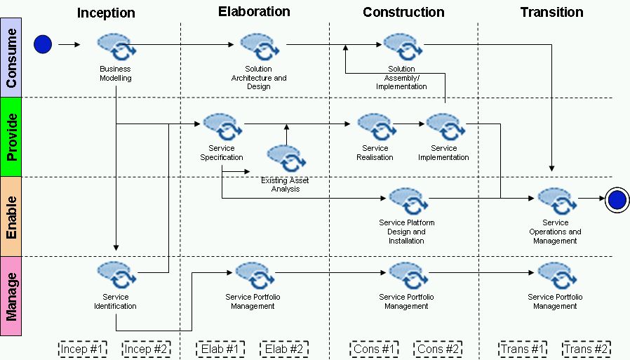
In Part 2 I discussed how activities in a delivery process could be created from capability patterns that are comprised of tasks and/or activities. Capability patterns are reusable patterns which can be applied across a range of delivery processes. Capability patterns have input/output work products which together define the ‘contractual boundary’ to which performers of the capability pattern must conform. In this post I’ll take a look at what these work products are and how they form part of a contract between capability patterns.

The table below shows the set of work products that are used in the process I have been describing.

Work Product Description Notation
Service Catalogue Catalogue of all services owned or used by the enterprise. May be technical or business, legacy or new/to be provided. Usually implemented as a service registry. WSDL
Service Certificate Identifies a service that meets certain quality criteria. Text
Service Portfolio Plan Describes what services will be provided, when and by whom. Text
Service Portfolio Describes the entire collection of business services that an enterprise uses or plans to use. Text
Service Model Defines the complete hierarchy of business and technical services used or planned to be used by the enterprise. Can exist at a logical and physical level. Contains one or more Service Specifications. UML
Service Specification Defines a detailed specification for each service. Can exist at a logical and physical level. Text/WSDL
Deployed Service A service deployed in the service platform. Jave, MQ etc
Deployed Service Environment A deployed service platform. N/A

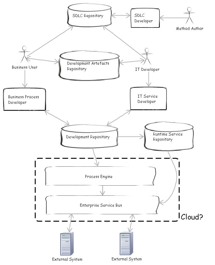
This diagram shows the relationships (finish to finish dependencies) between the above work products.

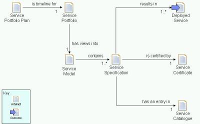
Work Product Dependency Diagram

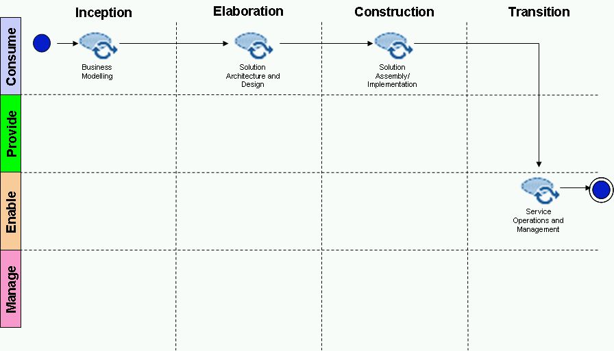
In this next diagram we can see how  what I’m referring to as ‘contractual boundaries’ can be realised using these work products which are passed between two of the capability patterns I discussed last time.

Contractual Boundaries

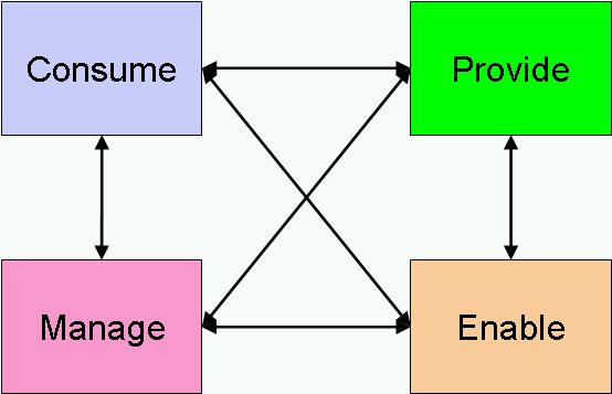
Activities produce one or more work products which are consumed by other activities, either in the same capability pattern, or in a different one. This means that provided the input and output work products are agreed the capability patterns can run in parallel or, if needed, at different times. So, one capability pattern, the ‘provide capability’ one in the above example can contribute to the Service Model work product which another capability pattern, the ‘manage service portfolio’ one can contribute to at a later time if need be. Having a common set of agreed work products, which are shared in a repository, becomes the key to having an effective delivery process.

A Service Based Development Process – Part 2

The basic Service Based Development Process I described previously described an end-to-end delivery process for creating services, whether these be cloud-based services or traditional ones running on a an enterprise service bus. The process consisted of a number of activities (where an activity groups together several tasks) as follows:

  • Business Modelling – Develop business process models to understand the business activities that need to take place. Probably a mix of as-is and to-be as well as manual and automated activities.
  • Solution Architecture and Design – Create the architecture for the solution, decides what services are to be used, what platform and delivery environment (public/private cloud, ESB etc) will be used.
  • Solution Assembly/Implementation – Assemble the services into an application and implement using the appropriate technology. Hopefully much of this will be done using tools that generate the appropriate process flows and pull in the right services.
  • Service Identification – Decide what new services need to be specified (i.e. not already in the Service Portfolio).
  • Service Specification – Specify services, their contracts (functional and service levels).
  • Existing Asset Analysis – What assets does the enterprise already have that could be service enabled (legacy code that could be wrappered etc).
  • Service Realisation – Decide what technology will be used to implement services.
  • Service Implementation – Implement services using the chosen technology.
  • Service Platform Design and Installation – Having decided the service runtime environment design and install it. For cloud-based services this means procuring the right cloud resources.
  • Service Operations and Management – Manage and run the service.
  • Service Portfolio Management – Ensure the Service Portfolio kept up to date.

In the example process we have seen so far each of these activities is composed together in such a way that a complete solution can be built out of a set of services that are deployed into a run-time environment. But that is not the only way these activities can be composed. A better way is to compose activities into capability patterns. Capability patterns are comprised of tasks and/or activities that can be composed into ‘higher-order’ capability patterns or delivery processes. They are reusable patterns which can applied across a range of delivery processes. Capability patterns have input/output work products which together define the ‘contractual boundary’ to which performers of the capability pattern must conform (more on this next time).

The delivery process described in part 1 is actually comprised of four capability patterns, each of which could be a process in its own right, or composed into different delivery processes. The four capability patterns are:

  • Provide Capability: Create a new or updated business process/capability based on user requirements. Uses existing services or specifies new ones where needed. Uses tasks mainly from the Consume discipline group.
  • Provide Service: Specify, design and build a new service according to business need. Certify, publish and deploy the service into the operational environment. Uses tasks mainly from the Provide discipline group.
  • Manage Service Portfolio: Create and maintain a service portfolio with an initial set of specified services. Ensure services are certified. Uses tasks from the Manage group.
  • Provide Environment: Design, build, test, install and run a new environment capable of running services. Uses tasks mainly from the Enable group.

Using the same diagrams as before here are the above four capability patterns laid out in terms of disciplines and phases from OpenUP.

Provide Capability
Provide Service
Manage Service Portfolio
Provide Environment

In the third part I’ll look at the work products which together define the ‘contractual boundary’ to which performers of each of the capability patterns must conform.

The ideas in this blog were jointly developed with my ex-IBM colleague Bruce Anderson.

A Service Based Development Process – Part 1

I have been toying around with this for quite a while. What prompted me to return to it was:

  1. With the cloud hype curve reaching its peak I feel compelled to join in, in one of the ways I know best, method, process and architecture.
  2. It allows me to further discuss the power of using an open, method framework based approach to building delivery processes in a plug-and-play kind of way.

I originally thought of calling this “A Cloud Service Based Development Process” however I think the word ‘Cloud’ is redundant. Whilst this process could be used for developing services “in the cloud” it is actually a generic process that can be used for developing services wherever they may actually be deployed. The process is based on three major components, all of which are in the public domain. All I’m doing is what architects are supposed to do, namely assemble components in new and interesting ways.

  1. Service Based Disciplines (from the CBDI), see here.
  2.  The Open Unified Process (from the OMG’s OpenUP), see here.
  3. The concept of activities and capability patterns from the Software and Systems Process Engineering  Metamodel (also from the OMG), see here.

The process emphasizes the organisational and contractual boundaries for a service-oriented enterprise (SOE) by a separation of concerns into a number of disciplines as follows: 

  • The service consumer and service provider are clearly separated as these require different skills and can be done by different teams. 
  • Enabling of SOA via the SO environment is a concern of its own (for example an ESB supports the implementation of services but does not affect their business content). 
  • Governance (manage) is integrated into everyday work. Example: negotiating the interface for a business service. 

These disciplines (concerns) are shown below.

Process phases are from OpenUP and are: 

  • Inception: Establish scope and define acceptance criteria. Identify key requirements, define candidate architecture and estimate the overall cost and schedule with detailed estimates for the elaboration phase. Identify risks and prepare the supporting environment. 
  • Elaboration: Establish a baselined architecture, produce an evolutionary prototype of production-quality components, as well as possibly one or more exploratory, throw-away prototypes to mitigate specific risks. Demonstrate that the baselined architecture will support the requirements and establish the supporting environment. 
  • Construction: Complete the analysis, design, development and testing of all required functionality. Iteratively and incrementally develop a complete product that is ready to transition to its user community. Establish that users are ready for the application to be deployed. 
  • Transition: Perform user and acceptance testing to validate the new system against user expectations. Convert operational databases. Ensure users and maintainers and ready to use the system. Perform deployment-specific engineering such as cut-over, commercial packaging and production, sales roll-out, field personnel training. Achieve stakeholder concurrence that deployment baselines are complete and user self-supportability. 

In the diagram below I show how the OpenUP phases combined with the previously mentioned disciplines can be overlayed with a deliver process for creating and deploying services.

The process is shown at the level of activities. An activity groups together one or more tasks and tasks deliver artefacts created by roles. I’ll detail more what each of these activities consist of in the next blog.
The other aspect to this diagram is that of iterations. As I’ve mentioned elsewhere I  believe the agile versus waterfall debate is essentially dead. We should deploy whatever processes make most sense for a particular project that can be accomplished in the most time efficient way possible. Using iterations usually makes sense so any process needs to allow for this as does this one. Each phase is iterative meaning that each iteration has elements of each discipline. You can view iterations as a wave which flows through the end-to-end process, early on the emphasis is on business modelling but also includes elements from the other disciplines whereas later on the emphasis shifts to operations and management even though the business process may still be being refined. 

Like I say, next time I’ll look at what each of the activities in this service based development process consists of and what artefacts they create.

How to Avoid the Teflon Architecture Syndrome

So you’ve sent all of your budding architects on TOGAF (or similar) training, hired in some expensive consultants in sharp suits to tell you how to “do architecture” and bought a pile of expensive software tools (no doubt from multiple vendors) for creating all those architecture models  you’ve been told about but for some reason you’re still not getting any better productivity or building the more reliable systems you were expecting from all this investment. You’re still building siloed systems that don’t inter-work, you’re still misinterpreting stakeholder requests and every system you build seems to be “one-of-a-kind”, you’re not “leveraging reuse” and SOA seems to be last years acronym you never quite got the hang of. So what went wrong? Why isn’t architecture “sticking” and why does it seem you have given yourselves a liberal coating of Teflon.The plain fact of the matter is that all this investment will not make one jot of difference if you don’t have a framework in place that allows the architects in your organisation to work together in a consistent and repeatable fashion. If it is to be effective the architecture organisation needs careful and regular sustenance. So, welcome to my architecture sustenance framework*.

Here’s how it works, taking each of the above containers one at a time:

  • Common Language: Architects (as do any professionals) need to speak the same, common language. This needs to be the foundation for everything they do. Common languages can come from standards bodies (UML and SPEM are from the OMG, IEEE 1471-2000 is the architecture description standard from the IEEE) or may be ones your organisation has developed and is in your own glossary.
  • Community: Communities are where people come together to exchange ideas, share knowledge and create intellectual capital (IC) that can be shared more broadly in the organisation. Setting up an architecture Community of Practice (CoP) where your thought leaders can share ideas is vital to making architecture stick and become pervasive. Beware the Ivory Tower Antipattern however.
  • Tools: If communities are to be effective they need to use tools that allow them to create and share information (enterprise social networking tools, sometimes referred to as Enterprise 2.0). They also need tools that allow them to create and maintain delivery processes and manage intellectual capital of all types.
  • Processes: Anything but a completely trivial system will need some level of system development lifecycle (SDLC) that enables it creation and brings a level of ceremony that the project team should follow. An SDLC brings order to the chaos that would otherwise ensue if people working on the project do not know what role they are meant to perform, what work products they are meant to create or what tasks they are meant to do to create those work products. Ideally processes are defined by a community that understands, not only the rules of system development, but also what will, and what will not, work in the organisation. Processes should be published in a method repository so that everyone can easily access them.
  • Guidance: Guidance is what actually enables people to do their jobs. Whereas a process shows what to create when, guidance shows how to create that content. Guidance can take many forms but some of the most common is examples (how did someone else do it), templates (show me what I need to do so I don’t start with a blank sheet every time) and guidelines (provide me with a step-by-step guide on how to perform my task) and tool mentors (how can I make use of a tool to perform this task and create my work product). Guidance should be published in the same (method) repository as the process so it is easy to jump between what I do as well as how I do it.
  • Projects: A project is the vehicle for actually getting work done. Projects follow a process, produce work products (using guidance) to deliver a system. Projects (i.e. the work products they produce) are also published in a repository though ideally this will separate from the generic method repository. Projects are “instances” of a delivery process which is configured in a particular way for that project. The project repository stores the artefacts from the project which serve as examples for others to use as they see fit.
  • Project and Method Repositories: The place where the SDLC and the output of multiple projects is kept. These should be well publicized as the place people know to go to to find out what to do as well as what others have done on other projects.

All of the above elements really do need to be in place to enable architecture (and architects) to grow and flourish in an organisation. Whilst these alone are not a guarantee of success without them your chances of creating an effective architecture team are greatly reduced.

*This framework was developed with my colleague at IBM, Ian Turton.