Reusable Assets for Architects

Architects are fond of throwing terms around which have mixed, ambiguous or largely non-existent formal definitions. Indeed one of the great problems (still) of our profession is that people cannot agree on the meanings of many of the terms we use everyday. There is no ‘common language’ that all architects speak. If you want to see some examples look up terms like ‘enterprise architecture’ or ‘cloud computing’ in wikipedia then look at what’s written in the ‘discussion’ section.Three terms that often get misused or are used interchangeably fall under the general category of reusable assets. A reusable asset is something which has been proven to be useful, in some form or another, in one project or architectural definition and could be reused elsewhere. The Object Management Group (OMG) defines a reusable asset as one that: provides a solution to a problem for a given context. See the OMG Reusable Asset Specification. Those of you familiar with the classic Design Patterns book by the so called “Gang of Four” will recognise elements of this definition from that book. Indeed reusable assets are a generalization of design patterns. Three other reusable assets, which are of particular use to an architect, are:

  • Reference architectures
  • Application frameworks
  • Industry solutions

What do each of these mean, what’s the difference and when (or how) can they be used?

A reference architecture is a template which shows, usually at a logical level, a set of components and their relationships. Reference architectures are usually created based on perceived best-practice at the time of their creation. This is both a good thing (you get the latest thinking) but can also be bad (they can become dated). Reference architectures are usually associated with a particular domain which could either be a business (e.g. IBM’s Insurance Application Architecture or IAA) or industry (such as a banking reference architecture) or technology domain (e.g. cloud and SOA). Ideally reference architectures will not preordain any technology and will allow multiple vendors products to be mapped to each of the components. Sometimes vendors use reference architectures as a way of placing their tools or products into a cohesive set of products that work together.

An application framework represents the partial implementation of a specific area of a system or an application. Reference architectures may be composed of a number of application frameworks. Probably one of the best known application frameworks is Struts from the Apache open source organisation. Struts is a Java implementation of the Model-View-Controller pattern which can be ‘completed’ by developers for their own applications.

Finally an industry solution is a set of pre-configured (or configurable) software components designed to meet specific business requirements of a particular industry. Industry solutions are usually created and sold by software vendors and are based on their own software products. However the best solutions adhere to open standards and would allow other vendors products to be used as well. Most organisations want to avoid vendor lock-in and are unlikely to take the “whole enchilada”. Industry solutions may be implementations of one or more reference architectures. For example IBM’s Retail Industry Framework implements reference architectures from a number of domains (supply chain, merchandising and product management and so on).

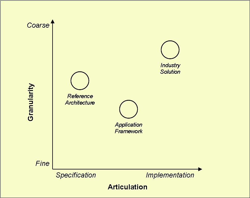
Assets can be considered in terms of their granularity (size) and their level of articulation (implementation). Granularity is related to both the number of elements that comprise the asset and the asset’s impact on the overall architecture. Articulation is concerned with the extent to which the asset can be considered complete. Some assets are specifications only, that is to say are represented in an abstract form, such as a model or document. Other assets are considered to be complete implementations and can be instantiated as is, without modification. Such assets include components and existing applications. The diagram below places the three assets I’ve discussed above in terms of their granularity and articulation.

There are of course a whole range of other reusable assets: design patterns, idioms, components, complete applications and so on. These could be classified in a similar way. The above are the ones that I think architects are most likely to find useful however.

Applying Architectural Tactics

The use of architectural tactics, as proposed by the Software Engineering Institute, provides a systematic way of dealing with a systems non-functional requirements (sometime referred to as the systems quality attributes or just qualities). These can be both runtime qualities such as performance, availability and security as well as non-runtime such as maintainability, portability and so on. In my experience, dealing with both functional and non-functional requirements, as well as capturing them using a suitable modeling tool is something that is not always handled very methodically. Here’s an approach that tries to enforce some architectural rigour using the Unified Modeling Language (UML) and any UML compliant modeling tool.

Architecturally, systems can be decomposed from an enterprise or system-wide view (i.e. meaning people, processes, data and IT systems), to an IT system view to a component view and finally to a sub-component view as shown going clock-wise in Figure 1. These diagrams show how an example hotel management system (something I’ve used before to illustrate some architectural principles) might eventually be decomposed into components and sub-components.

Figure 1: System Decomposition

This decomposition typically happens by considering what functionality needs to be associated with each of the system elements at different levels of decomposition. So, as shown in Figure 1 above, first we associate ‘large-grained’ functionality (e.g. we need a hotel system) at the system level and gradually break this down to finer and finer grained levels until we have attributed all functionality across all components (e.g. we need a user interface component that handles the customer management aspects of the system).

Crucially from the point of view of deployment of components we need to have decomposed the system to at least that of the sub-component level in Figure 1 so that we have a clear idea of each of the types of component (i.e. do they handle user input or manage data etc) and know how they collaborate with each other in satisfying use cases. There are a number of patterns which can be adopted for doing this. For example the model-view-controller pattern as shown in Figure 2 is a way of ascribing functionality to components in a standard way using rules for how these components collaborate. This pattern has been used for the sub-component view of Figure 1.

Figure 2: Model-View-Controller Pattern

So far we have shown how to decompose a system based on functional requirements and thinking about which components will realise those requirements. What about non-functional requirements though? Table 1 shows how non-functional requirements can be decomposed and assigned to architectural elements as they are identified. Initially non-functional requirements are stated at the whole system level but as we decompose into finer-grained architectural elements (AKA components) we can begin to think about how those elements support particular non-functional requirements also. In this way non-functional requirements get decomposed and associated with each level of system functionality. Non-functional requirements would ideally be assigned as attributes to each relevant component (preferably inside our chosen UML modelling tool) so they do not get lost or forgotten.

Table 1
System Element Non-Functional Requirement
Hotel System (i.e. including all actors and IT systems). The hotel system must allow customers to check-in 24 hours a day, 365 days a year. Note this is typically the accuracy non-functional requirements are stated at initially. Further analysis is usually needed to provide measurable values.
Hotel Management System (i.e. the hotel IT system). The hotel management system must allow the front-desk clerk to check-in a customer 24 hours a day, 365 days a year with a 99.99% availability value.
Customer Manager (i.e. a system element within the hotel’s IT system). The customer manager system element (component) must allow customer details to be created, read or updated (but not deleted) 24 hours a day, 365 days a year with a 99.99% availability value.
Customer Manager Interface (i.e. the user interface that belongs to the Customer Manager system element). The customer manager interface must allow customer details to be created, read or updated (but not deleted) 24 hours a day, 365 days a year with a 99.99% availability value.

Once it is understood what non-functional requirement each component needs to support we can apply the approach of architectural tactics proposed by the Software Engineering Institute (SEI) to determine how to handle those non-functional requirements.

An architectural tactic represents “codified knowledge” on how to satisfy non-functional requirements by applying one or more patterns or reasoning frameworks (for example queuing or scheduling theory) to the architecture. Tactics show how (the parameters of) a non-functional requirement (e.g. the required response time or availability) can be addressed through architectural decisions to achieve the desired capability.

In the example we are focusing on in Table 1 we need some tactics that allow the desired quality attribute of 99.99% availability (which corresponds to a downtime of 52 min, 34 sec per year) to be achieved by the customer manager interface. A detailed set of availability tactics can be found here but for the purposes of this example availability tactics can be categorized according to whether they address fault detection, recovery, or prevention. Here are some potential tactics for these:

  • Employing good software engineering practices for fault prevention such as code inspections, usability testing and so on to the design and implementation of the interface.
  • Deploying components on highly-available platforms which employ fault detection and recovery approaches such as system monitoring, active failover etc.
  • Developing a backup and recovery approach that allows the platform running the user interface to be replaced within the target availability times.

As this example shows, not all non-functional requirements can be realised suitably by a component alone; sometimes full-realisation can only be done when that component is placed (deployed) onto a suitable computer platform. Once we know what non-functional requirements need to be realised by what components we can then think about how to package these components together to be deployed onto the appropriate computer platform which supports those non-functional requirements (for example on a platform that will support 99.99% availability and so on). Figure 3 shows how this deployment can be modelled in UML adopting the Hot Standby Load Balancer pattern.

Figure 3: Deployment View

Here we have taken one component, the ‘Customer Manager’, and showed how it would be deployed with other components (a ‘Room Manager’ and a ‘Reservation Manager’’) that support the same non-functional requirements onto two application server nodes. A third UML element, an artefact, packages together like components via a UML «manifest» relationship. It is the artefact that actually gets placed onto the nodes. An artefact is a standard UML element that “embodies or manifests a number of model elements. The artefact owns the manifestations, each representing the utilization of a packageable element”.

So far all of this has been done at a logical level; that is there is no mention of technology. However moving from a logical level to a physical (technology dependent level) is a relatively simple step. The packaging notion of an artefact can equally be used for packaging physical components, for example in this case the three components shown in Figure 3 above could Enterprise Java components or .NET components.

This is a simple example to illustrate three main points:

  1. Architecting a system based on functional and non-functional requirements.
  2. Use of a standard notation (i.e. UML) and modelling tool.
  3. Adoption of tactics and patterns to show how a systems qualities can be achieved.

None of it rocket science but something you don’t see done much.